1. VIC 3D Object Detection
VIC 3D object detection is to locate and identify 3D objects using information from both vehicle and infrastructure sides. The challenge is to improve detection precision using multi-view, multi-modality, temporal-spatial asynchronous data, under the limitation of communication bandwidth.
1.1 Problem Formulation
Input: vehicle-side multi-modality data, infrastructure-side multi-modality data, corresponding timestamp files, and calibration files.
Objective:
- Improve 3D detection precision
- Reduce data usage from infrastructure-side, with similar detection precision
- Reduce the number of sensors used, with similar detection precision
1.2 Evaluation Metrics
Detection Precision: evaluating the precision of 3D object detection with PASCAL criteria.
Communication Cost: evaluating the amount of data used from infrastructure-side.
1.3 VIC 3D Object Detection Baseline
We implemented the baseline framework for VIC 3D object detection. It's a late fusion approach.
- Firstly, we train the vehicle-side 3D object detectors on DAIR-V2X-V and part of DIAR-V2X-C, and the infrastructure-side 3D object detector on DAIR-V2X-I and part of DAIR-V2X-C.
- Then, we use the trained 3D object detectors to detect 3D objects from vehicle-side and infrastructure-side data separately.
- We transform the detected 3D objects from the Local Coordinate System to the Virtual World Coordinate System.
- We use the late fusion method to integrate vehicle and infrastructure side results.
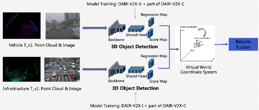 Fig. Baseline Framework
2. Data Collection
A. Scene Setting
1. Infrastructure-side Equipment: Deployed Cameras and LiDARs on the selected intersections with complex traffic scenes in the Beijing High-Level Autonomous Driving Demonstration Area, synchronized GPS timing, and calibrated intrinsic and extrinsic matrices of sensors
2. Vehicle-side Equipment: Equipped autonomous-driving vehicles with Cameras and LiDARs, synchronized GPS timing, and calibrated intrinsic and extrinsic matrices of sensors
3. Route Planning: Driven autonomous-driving vehicles through these selected intersections
4. Data Segment: Selected data segments that both sides are at the same time and space
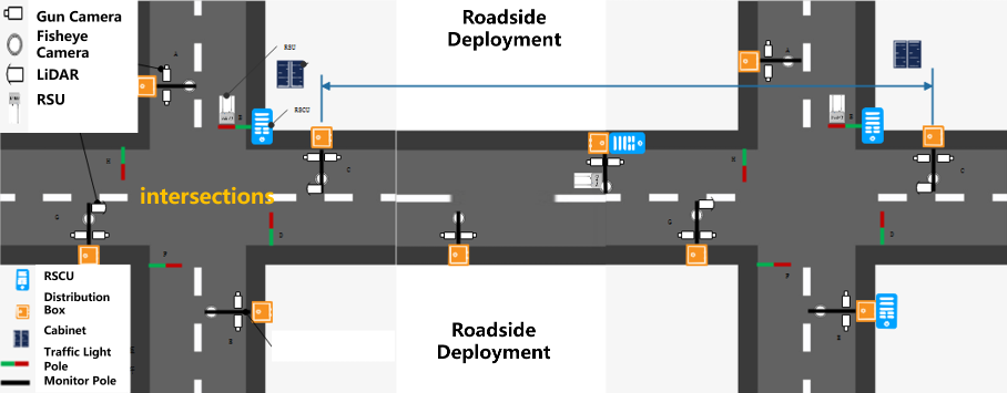
B.Infrastructure-side Equipment
LiDAR(300p)
- 10Hz capture frequency
- 100° Horizontal FOV, 40° Vertical FOV
- 280m maximum detection range
- <=3cm detection distance accuracy
Camera
- 1'' CMOS sensor of global exposure
- 25Hz capture frequency
- JPEG images in RBG format of 1920x1080 resolution
C. Vehicle-side Equipment
One LiDAR on the top of the vehicle and a front-view
Camera.
LiDAR (Hesai Pandar 40p)
- 10Hz capture frequency
- 360° Horizontal FOV, 40° Vertical FOV
- 200m maximum detection range, 10% reflectivity
- 0.33° minimum vertical resolution
Camera
- 20Hz capture frequency
- 128° Horizontal FOV, 77° Vertical FOV
- JPEG images in RBG format of 1920x1080 resolution
D. Calibration and Coordinate System
To achieve a high-quality multi-sensor dataset, it is essential to do spatial synchronization as follows.
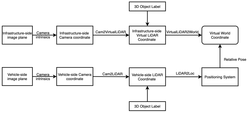 Fig. Conversion between Different Coordinate Systems
- Virtual World Coordinate System
The origin of the Virtual World Coordinate System is located at a random point on the earth, the x-y plane is parallel to the ground plane, and the z-axis is positive upwards.
- LiDAR Coordinate System
The origin of the LiDAR Coordinate System is located at the center of the LiDAR sensor, the x-axis is positive forwards, the y-axis is positive to the left, and the z-axis is positive upwards.
- Virtual LiDAR Coordinate System
The origin of the Virtual LiDAR Coordinate System is located at the center of the LiDAR sensor, the x-y plane is parallel to the ground plane, and the z-axis is positive upwards.
- Camera Coordinate System
The origin of the Camera Coordinate System is placed at the center of the lens, the x-y plane is parallel to the image plane, and the z-axis is positive forwards.
- Image Coordinate System
The Image Coordinate System is a 2D coordinate system where the origin is at the top-left of the image, and the x-axis and the y-axis are along the image width and height respectively.
- Positioning System
The real-time position and orientation angle of an autonomous vehicle can be obtained using GPS/IMU. Real-world location is further transformed to the Virtual World Coordinate System to ensure data security and facilitate research.
E. Synchronization
GPS time service is used to synchronize data captured from both infrastructure-side and vehicle-side sensors.
3. Data annotation
Data Sampling
Data is collected by both vehicle-side and infrastructure-side sensors when an autonomous vehicle passes the intersection. About 100 segments of 20s+ sequential data are extracted and then sampled at a frequency of 10Hz.
3D Annotation
2D and 3D bounding boxes of the obstacle objects are provided as well as their category attribute, occlusion state, and truncature state in the annotation. Note that the 3D bounding boxes are located in the Virtual LiDAR Coordinate System. The format of the annotation is as follows.
- Type. 15 object classes, including Car, Pedestrian, Cyclist, etc. PedestrianIgnore means pedestrian objects with less than 15*15 pixels or more than 4/5 occluded. CarIgnore means car objects with less than 15*15 pixels or more than 4/5 occluded. OtherIgnore means other objects with less than 15*15 pixels or more than 4/5 occluded.
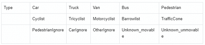 Table. 3D Object Type Classes
- Truncated. Interger (0, 1, 2) indicating truncated state. 0 = non-truncated, 1 = transversely truncated, 2 = longitudinally truncated.
- Occluded. Integer (0, 1, 2) indicating occlusion state. 0 = fully visible, 1 = partly occlued, 2 = largely occluded.
- Alpha. Observation angle of object, ranging [-pi, pi]
- 2D box. 2D bounding box of object in the image.
- 3D box. 3D bounding box of object in Virtual LiDAR Coordinate System, including the (height, width, length, x_loc, y_loc, z_loc) of objects in meters, and (rotation_y) of the angle at which an object rotates about the y-axis in Virtual LiDAR Coordinate System.
Vehicle-Infrastructure Collaborative (VIC) Annotation
Based on the labeled data from both vehicle-side and infrastructure-side, we take point cloud timestamp from vehicle-side as the VIC annotation timestamp. The collaborative annotation results are as follows.
- Vehicle-side Annotation: using vehicle-side 3D labeled data to evaluate the VIC fusion results.
- Vehicle-Infrastructure Collaborative Annotation: selecting data pairs with less than 10 ms time difference between
vehicle-side and infrastructure-side data. Annotation results are fused in the Virtual World Coordinate System.
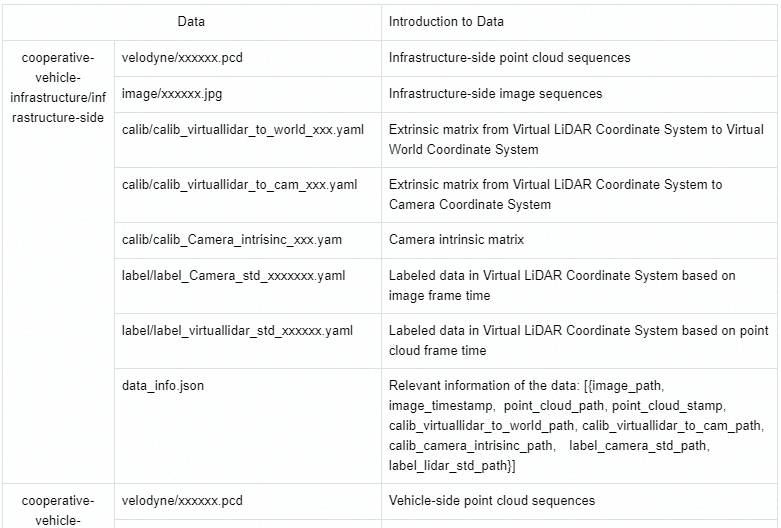
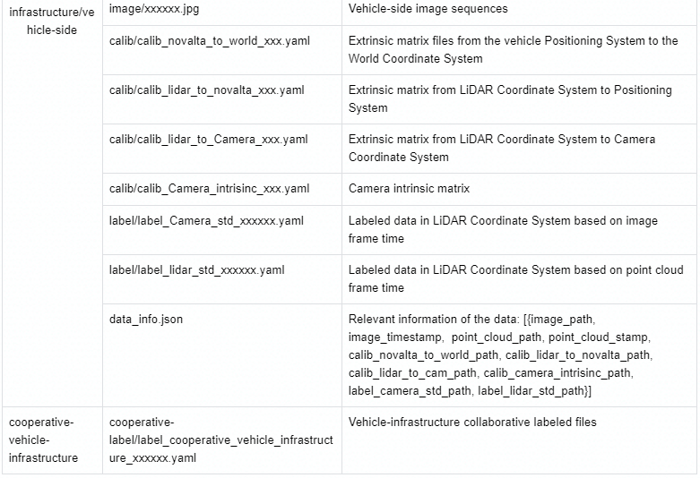
4. Dataset Format